A-Arm Track Locator
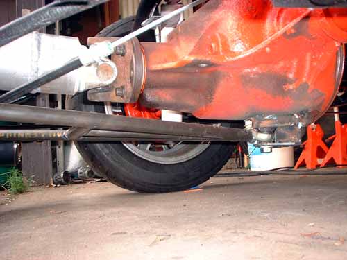
I probably agonized over this issue for the longest out of any thing to date - what was the best means to provide lateral track location for the axle and a way to control axle spool up due to torque.
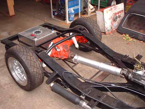
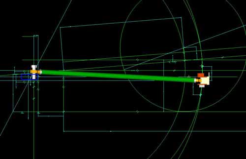
I had originally planned to use the Global West torque arm I found on Ebay as my traction device, but I started having second thoughts the further I got into it. I took measurements of the frame and axle and laid out the dimensions in EDS I-deas10NX which is the 3D CAE modeling application I use most in my business. First item I modeled were the spherical rod ends and their joint constraints.
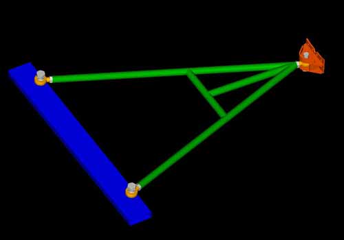
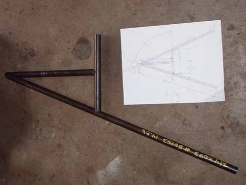
Then I began investigating the alternatives - Panhard bar or Watts-link combined with a torque-arm, or an a-arm. After working out a number of solutions, I found the a-arm would work the best for both tasks, with the least amount of fabrication and weight. Below are some images from the CAE development .
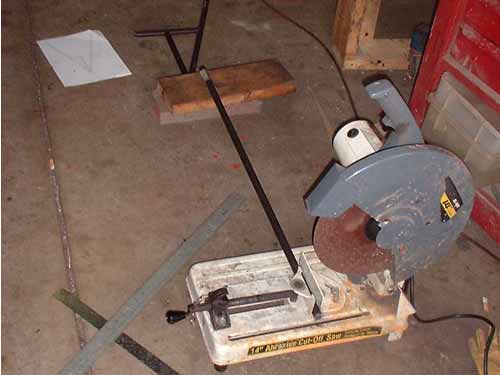
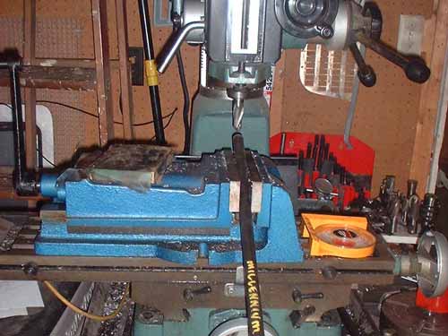
I bought some DOM (drawn over mandrel) heavy wall tube, and starting cutting the pieces I needed. Then the tubes were tapped to accept the rod ends.
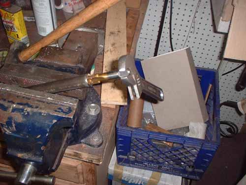
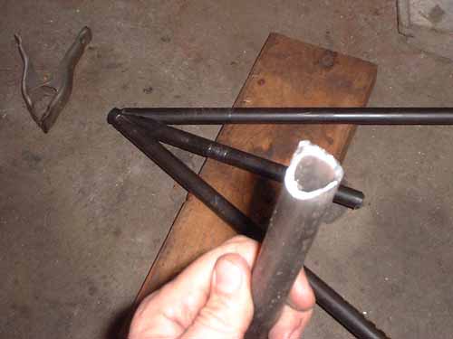
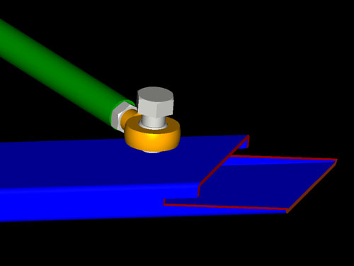
To get a really tight fit at the joints, I used my mill and a combination of straight and ball cutters to cut the "birdsmouths" in the ends for the angled joints. I have a tubing notcher that might have been quicker, but I didn't have a 7/8" bi-metal hole saw and running out to get one would would have taken the same amount of time........
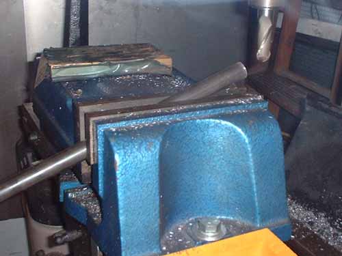
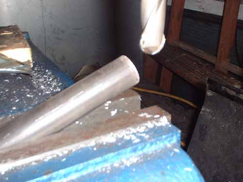
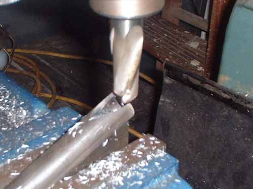
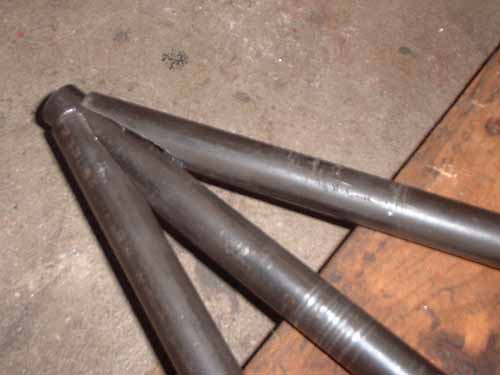
Here's a close-up of one of the birdsmouths, and a few pics of the test fitting. You can see from the close-up of the apex that the joints are a very snug fit pre-welding.
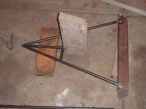
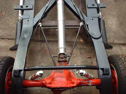
The cross-member is a length of 1x3x1/8" wall box tube. The ends were angle cut, then slits were made in the ends, and the top surfaces shortened so that the cross-member slips over over the lower flanges on the rear legs of the frame "X". The longer lower portions at the ends are welded to the underside of the factory reinforcing plates where the "X" meets the frame rails. The upper portions, above the slits, fit into the "X" and are welded to the vertical surfaces of the inside of the "X". It sits below the stock exhaust through hole, so this approach could be re-engineered to fit a "street" Roadster with a stock rear end.
After welding in the first cross tube in the "A", I decided that a second tube was needed down near the cross-member heim joints to add stiffness. We'll see how it does with hard cornering and acceleration trial runs in the spring.
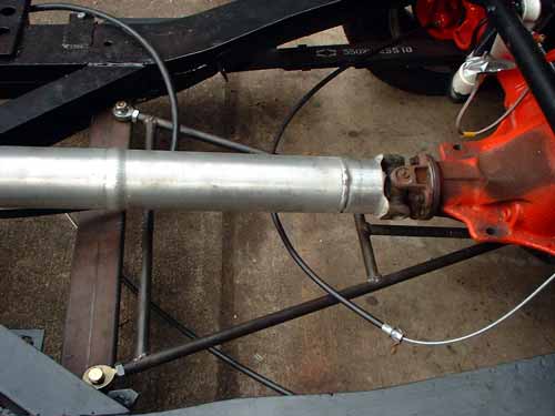
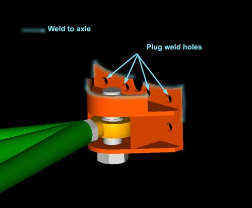
Here's the lower mount welded to the axle housing. It sits no lower than the oil pan. The rod end in the pic is not tightened down - that why its sitting at the funky angle. I still have to dis-assemble and finish painting the components.