Steering Modifications
Since the V6 is wider ( understatement ) than the original inline 4, the steering setup needed to be modified to clear the engine and headers. This would entail adding some u-joints and a support bearing, as well as modifying the column to support the short shaft the steering wheel mounts to.
The original setup is a "death spear" - a straight hardened shaft that goes directly from the u-joint on the steering gearbox, through the firewall, supported and guided by a tube with a couple of rubber vibration isolators.
I purchased a couple of Sweet Manufacturing steering u-joints and a spare, stock steering shaft. Much trial and error fitting was done using 0.750 dia. thin wall brass tubing cut in various lengths to mock up a linkage that would work. Since the new setup would require a multi-joint linkage, something needed to be done to support and capture the short shaft between the steering wheel and the first u-joint within the column tube. At the top of the column, under the steering wheel, a thrust bearing would be used to keep the wheel action smooth, and at the lower end, a sleeved needle bearing would keep the shaft and u-joint centered. The U-joint needed to be partially inside the tube for space reasons.
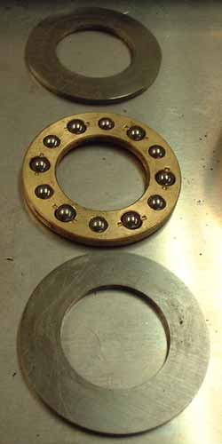
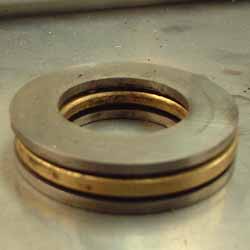
I found a couple of bearings at a local dealer that fit the bill. The thrust bearing has two hardened races with a central ball bearing carrier. I turned an aluminum spacer to fit under the lower race, inside the switch housing, to position the wheel and horn ring correctly. The assembly sequence is spacer, lower race, bearing, upper race, wedges, wheel, lock washer, and nut.
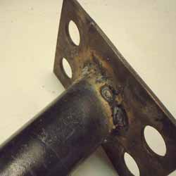
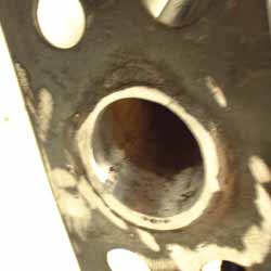
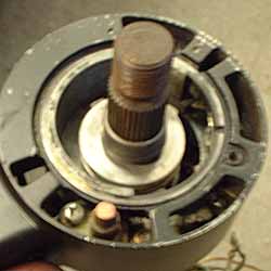
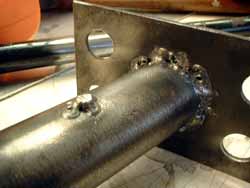
For the other end, first I had to modify the column so the U-joint would fit and not jam. I welded the tube / plate on the inside, then ground the tube almost flush with its mounting plate on the outside.
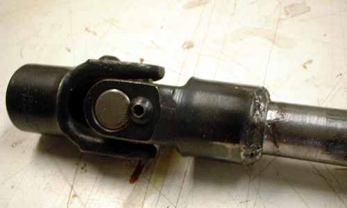
Then the U-joint was welded to the shaft, and I lathe cut a shoulder into the weld to ride against the sleeve bearing.
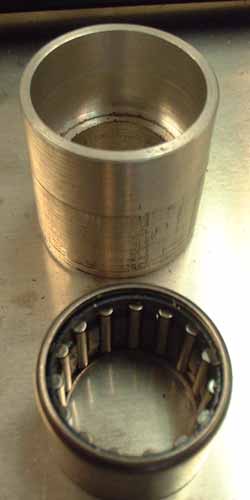
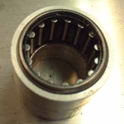
In order to position the sleeve bearing within the tube, capture the shaft, and create the necessary amount of free-play, I had to turn a bearing carrier that would press fit into the tube.
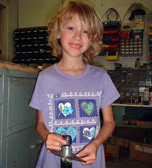
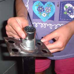
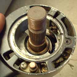
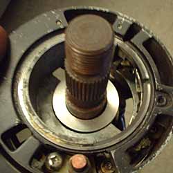
Here's my "Ace" mechanic Sydney showing the relationship of the bearing, carrier, and tube.
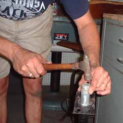
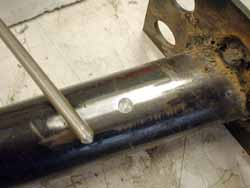
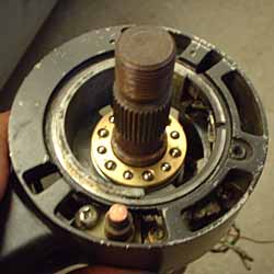
Here's me driving in the carrier with chunk of AL bar stock. The whole thing was assembled / disassembled several times to determine the right position of the carrier within the tube to give a small amount of free play to prevent compressing the thrust bearing at the other end. Once it was in just the right place, I drilled through the tube, and partially through the carrier's thick section. Took a piece of 3/16" rod, put a chamfer on the end to match the drill point angle, stuck it in the hole and welded it in place to pin the carrier in the correct place. Ground it smooth after taking the photo. Did this on both sides - probably overkill but........
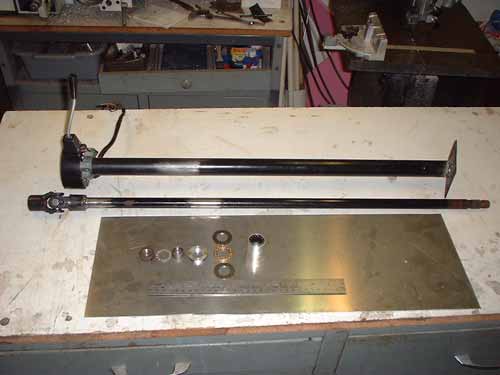
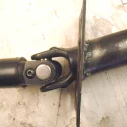
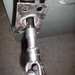
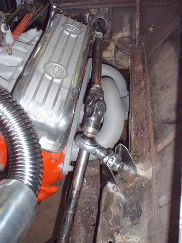
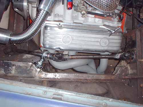
Here's a couple of shots of the completed linkage - everything moves smoothly and feel tight.
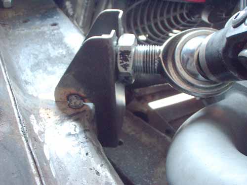
A close-up of the heim joint bracket - not finish welded, just tacked in place.
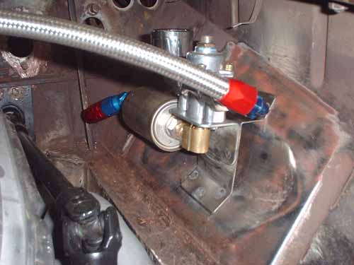
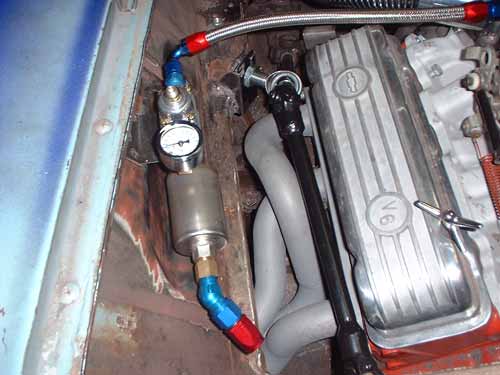
Also fabbed a bracket to mount the fuel-pressure regulator and filter - filter is from a C5 Corvette. AN-8 braided line will run from the rear of the car, and I'll be making an aluminum heat shield to mount on the body rail.