
Axle, Engine, and Transmission Rebuild
Before we get to the mechanical stuff...if you checked out the Body is Off! link, you'd know I found a mummified mouse stuck in the frame. Over the winter the mice had a "field day" in my shop, running up the open exhaust pipes and through the headers, stuffing the intake ports with seed. When we lifted the body again this spring, found another dried out mouse stuck in the same hole in the frame. My brother-in-law suggested a graphic for the "R" incorporating a mouse, so I whipped up the following which will probably get painted on the lower front fenders behind the wheel arches....
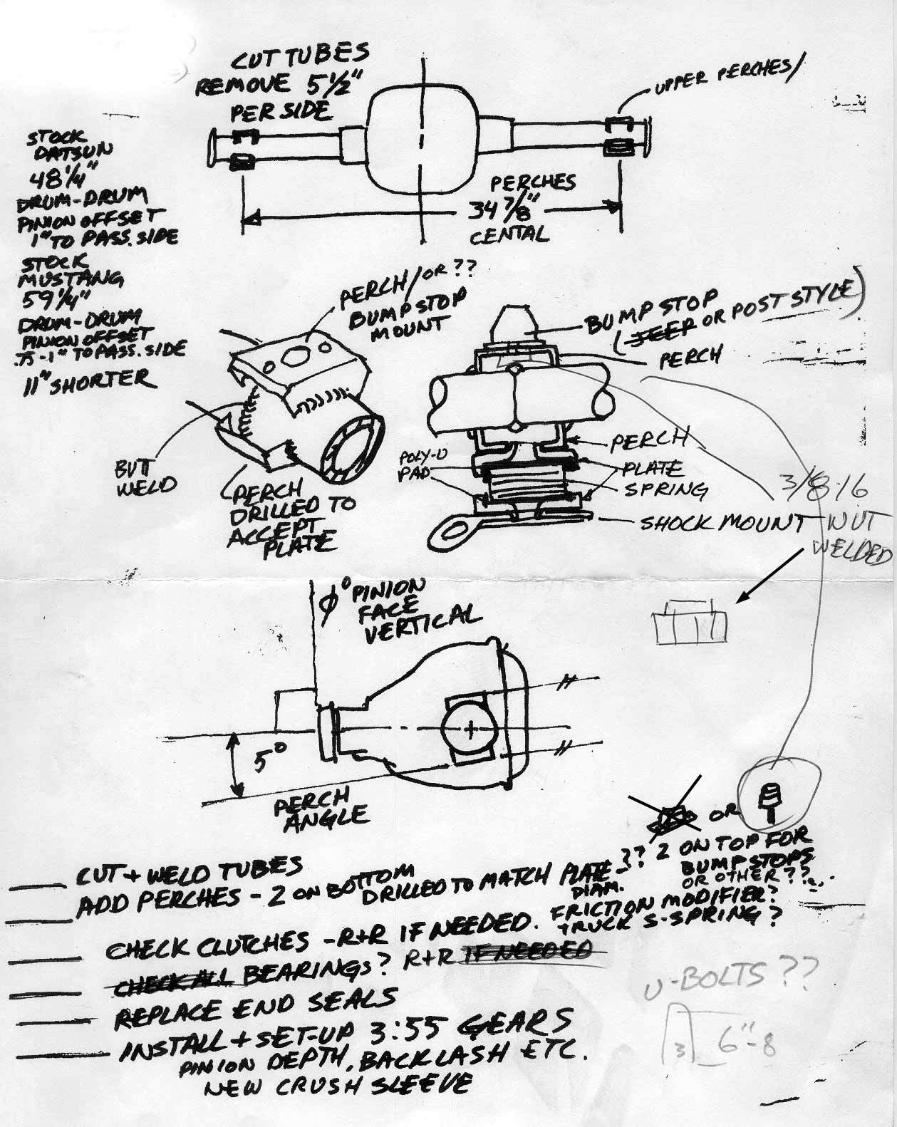
I've had lots of inquiries and requests for photos / details of using a Mustang 8.8 axle. Below is the sketch ( click for a hi-res printable version) I prepared for the "axle guy", a longtime drag racer who's currently running an 8 sec. Chrysler inline 6 rail. He's got a shop to die for, complete with a large Miller TIG welder.
The axle I bought was from a '93 Mustang GT, and the dimensions are to match the width of the wheel mounting flanges.
I took the housing, sketch, and 3.55 gear set to him and a week later the job was done. The tubes need cut by 5.5" per side, and new spring perches added 34.875" central. I had already cut / ground off all the stock brackets and mounts ( see Lots-o-stuff )
I also had him replace all the bearing, seals, and clutches, and had him set up the gear set. Probably could have done this myself, but he's a pro and I had others things to get done.
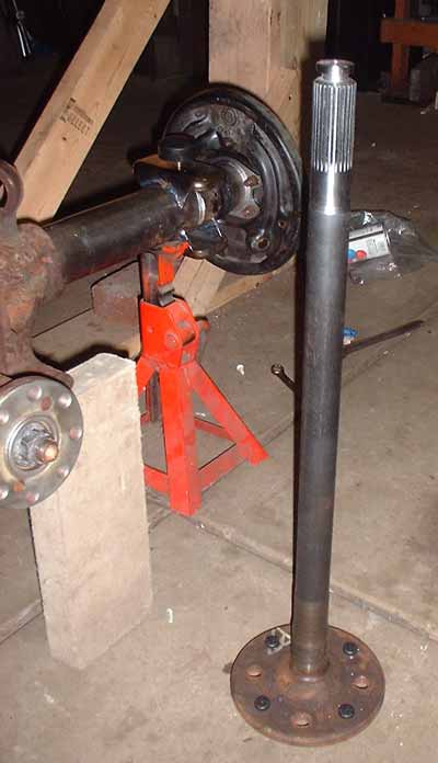
I sent the axle shafts off to Moser Engineering with instructions for them to cut each stock shaft down by 5.50" , re-spline with stock c-clip grooves, re-drill them to 4x4.5 bolt pattern, and press in new 7/16 x 1.25" studs to accommodate my stock pattern wheels. I re-drilled a new set of drums on the mill in my shop.
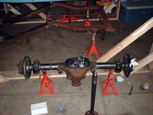
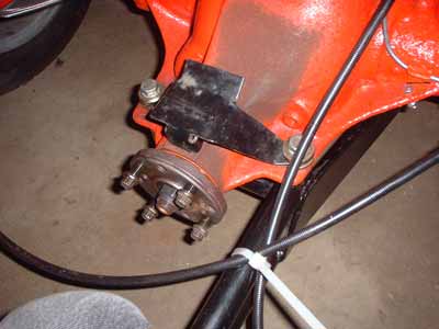
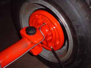
Here's the completed housing, with the axles and brakes being installed.
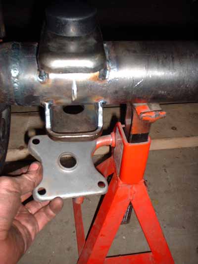
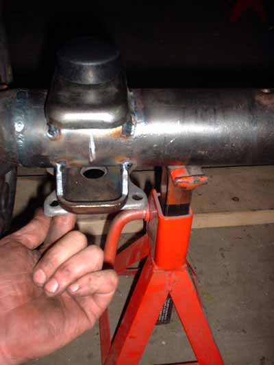
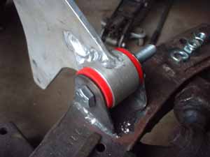
I had him enlarge the holes in the Moroso perches to accept the boss on the spring capture plates. I still need to elongate the holes in these and the shock mount plates to work with the wider ( 2.875 x 3/8 x 6.5") U-bolts needed for the 'stang axle. Also had him weld on an upper pair of perches, with a nut that has a shoulder cut in it to fit the hole, welded into the underside. This will let me pick and choose from a selection of screw-in stud-mount bump-stops from Energy Suspension to dial in the response.
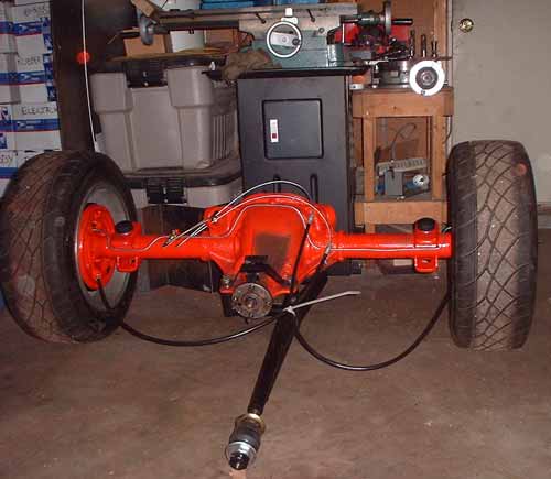
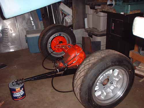
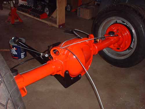
The arm mounted to the diff. is a Trac-link torque arm from Global West. I lucked out and found JUST the arm on Ebay, without all the Mustang mounting brackets, etc. I'll be fabricating a mount on the frame for it. Didn't finish painting the center section of housing since I plan on engineering a Watts Link which will utilize another scarfed stock bracket that mounts on the nose which will require some welding. Update - I will not be using this arm - see the A-arm page - I'll probably resell it on Ebay.
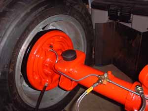
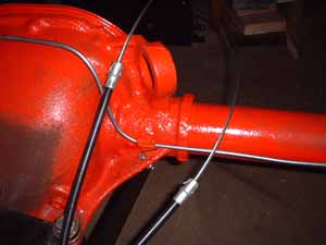
Hard line plumbing - 3/8-24 IFF "T" with 3/8-24 to -3AN adapter and flex line from Pegasus Racing. Clip at right of diff. was cut down piece scavenged from original Mustang hardware.
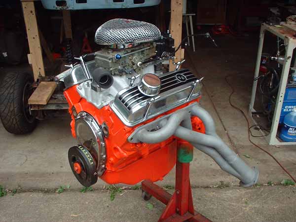
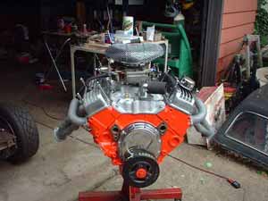
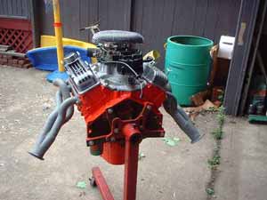
Here's a couple of shots of the engine assembled. Crisp and clean cheap horsepower. Desktop Dyno numbers with cam, manifold, carb CFM, porting, and header specs entered yields 245HP / 257 TQ at 5000RPM.
Crank was magnafluxed for cracks, then ground
.010/.010 and deburred.
Block was hot tanked, decks and mains alignment checked. Bored .030 and
honed. New freeze plugs, galley plugs, cam bearings.
Old pistons pressed off, rods reconditioned and shot blasted, ARP bolts.
New cast .030 flat top pistons. CR 9.35:1 232CID
During assembly, I added:
Hasting rings, Clevite bearings, Felpro Gaskets
Checked all clearance with Plastigage during assembly, and used Molykote
assembly lube.
Melling High volume oil pump and pickup, double-roller timing set, two piece
timing cover, new nodular iron balancer
Edlebrock cam:
.420 204
.443 214 at .050
Edlbrock dual-plane manifold
Rebuilt Holley 390CFM w/ vacuum secondaries - will have to jet it accordingly
when I fire the motor.
Heads: new valves, guides, springs, 3-angle seat job. I spent total of 18
hours port-matching, pocket-porting and polishing.
Rebuilt the HEI with new reluctor coil, pickup, module, springs weights, cap,
rotor, and Accel high voltage coil.
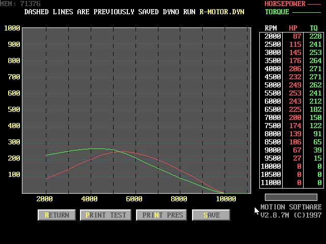
Here's a graph from Destop-Dyno
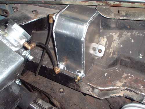
While working in the engine compartment, I've had this niggling apprehension about the engine mounts I had developed early on - not about their strength, but about the close proximity of the urethane biscuits to the headers. So when I found a 1/4" aluminum motor plate cheap on Ebay, I decided to change things. First there's a pic of the foam-core and wood template used to check the fit - always easier to cut foam-core, balsa, cardboard, or plywood than it is to cut metal, plus its you don't feel too bad when you have to make another, or another.............
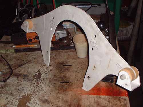
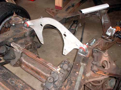
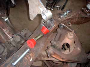
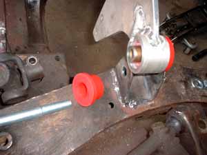
I cut the plate to a visually pleasant arched profile, turned a couple of 6061 aluminum tubes, and had the same welder who did my "puke" tank join them to the plate. Some stiff Urethane 4-bar bushings from Energy Suspension, and a couple of fabricated U-brackets finish it up. This plate bolts to the front of the block, the bushings have a bit of give, and are far enough away from the exhaust heat to get rid of that niggle.......
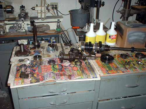
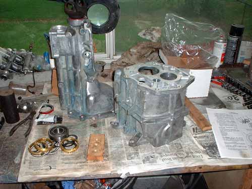
Tranny's still not together yet - rebuild kit was missing one part - but the main shaft, cluster, and all sychros are put together and I'm hoping to have it back in the case this week.